14+ thermopile wiring diagram
Searching for Thermopile Gas Valve Wiring Diagram Do you really need this document of Thermopile Gas. The DC setting will either say DC on your meter or a symbol.
How To Test Your Thermopile Www Mygasfireplacerepair Com
An alternative to bare wire ends is a thermocouple connector.
. The following image shows the 14 pin relay wiring diagram. 14 Thermostat Knob 177EGKNOB 15A Red Power Light. Air Conditioner Thermostat Wiring Details and Color Code.
It should be noted here that a relay is an electromagnetic switch with different rating voltage and. These connectors consist of a male plug and a female receiver pair and can be placed anywhere along your thermocouple wiring. Vatell Corporation 2002Because it is made with thin-film sputtering techniques the entire sensor is less than 2 mm thick Fig.
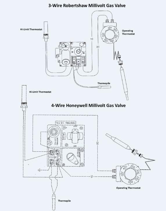
This is the GRID EYE an IR array sensor in a thermopile type infrared sensor develop by Panasonic which detects the amount of infrared rays. The Honeywell Q313 Thermopile generates 750 mV which is sufficient to operate an automatic millivolt gas control system independent of any outside power source. Official Post from AC SERVICE TECH.
January 14 2020 Thermopile Gas Valve Wiring Diagram read online. Wiring attic fan diagram switch master thermostat flow pt6 install pilot power. Hardy wood furnace wiring diagram.
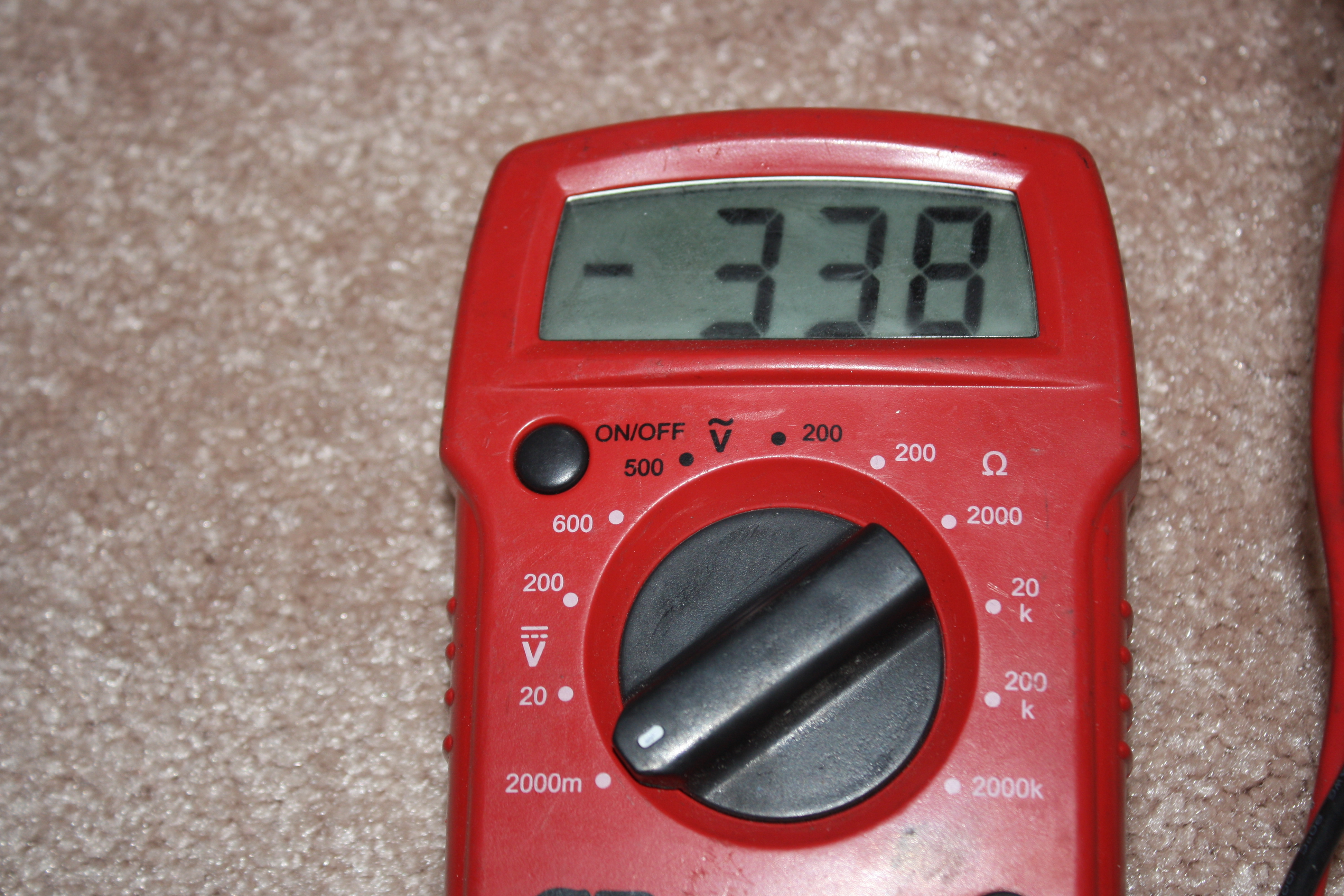
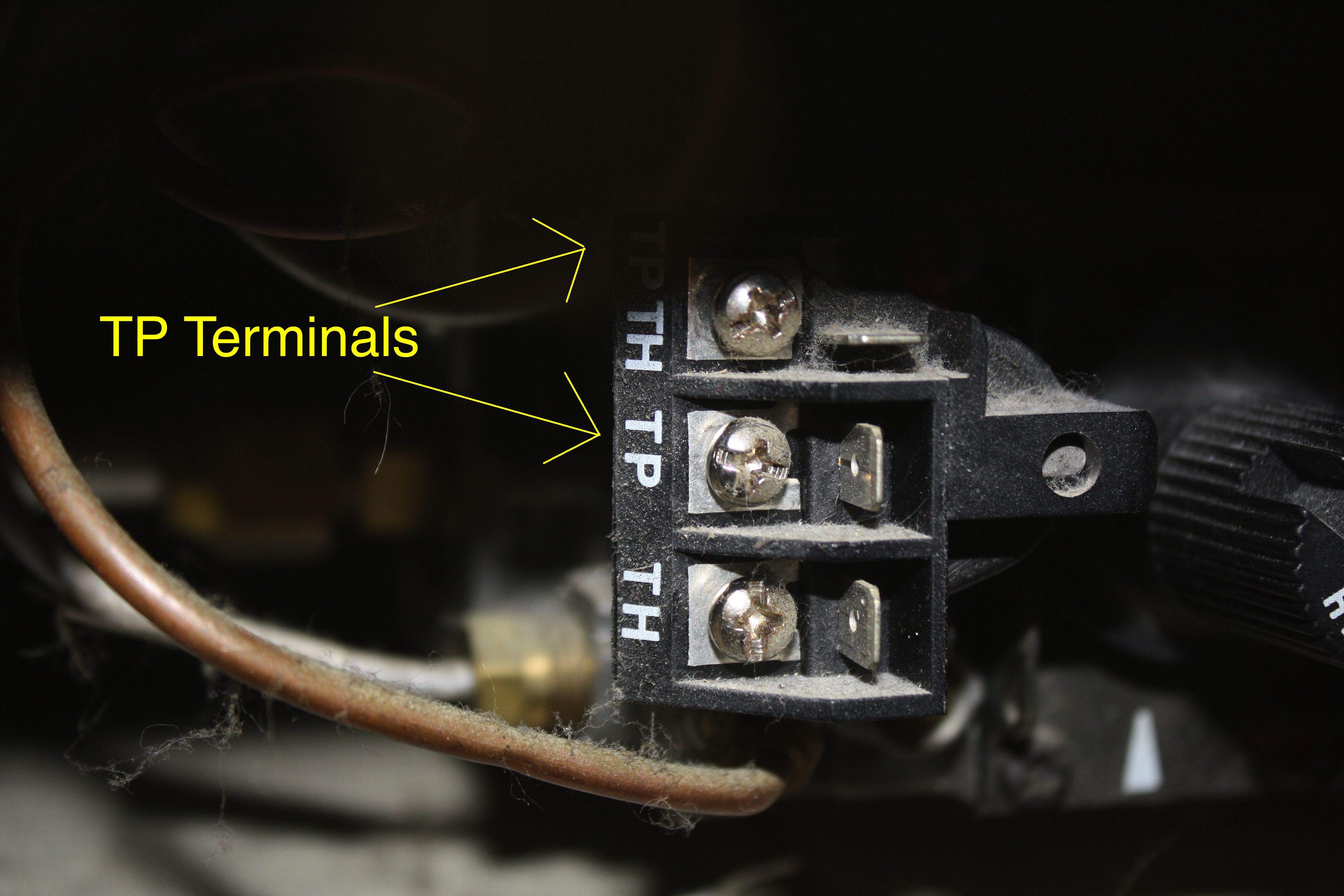
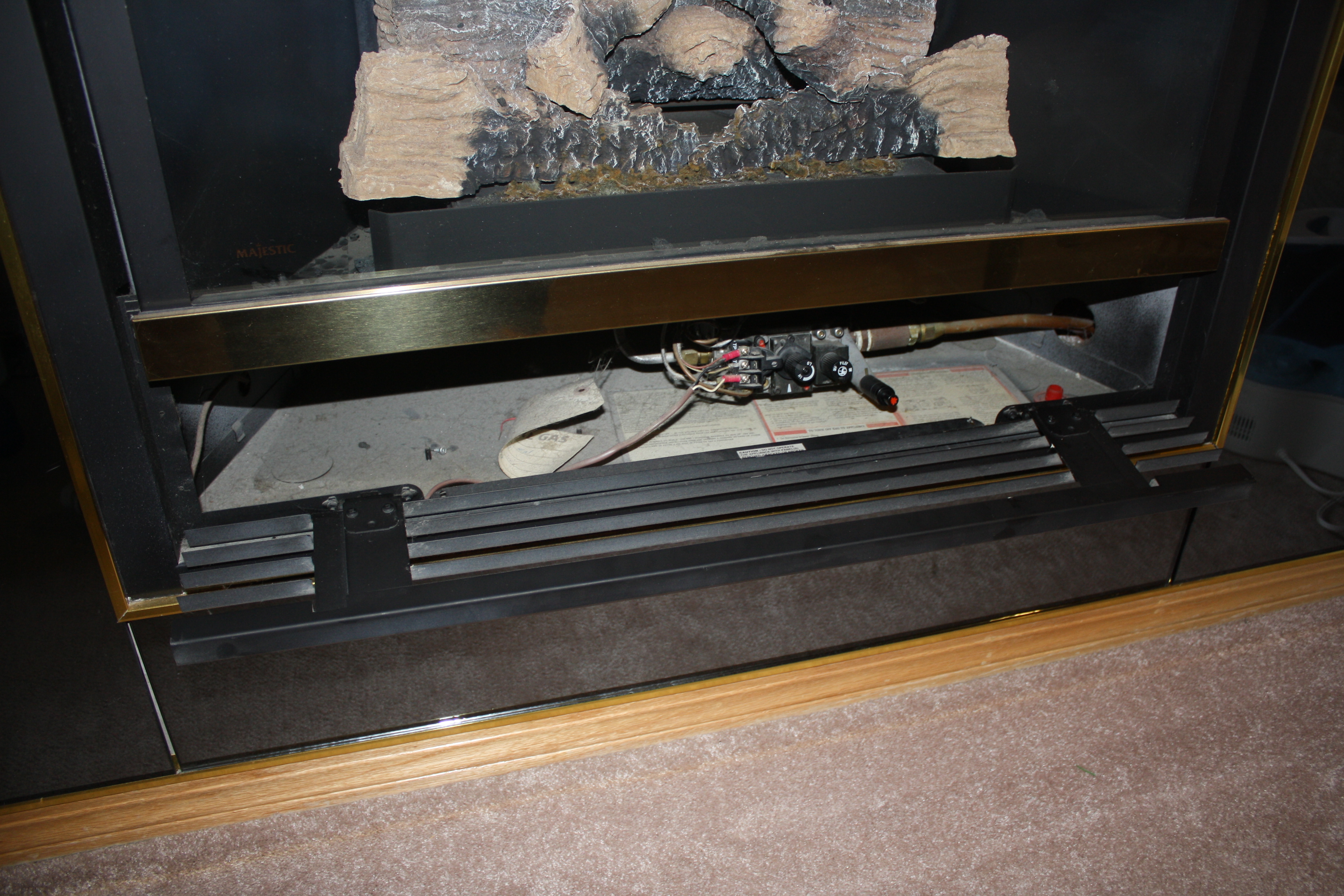
We can test the voltage using a digital multimeter on DC millivolt setting on the terminals that the thermopile is connected to. Wood Furnace Wiring Diagram - Style Guru. With these connectors you can join extension grade wire to thermocouple grade wire or connect two lengths of extension wire to make it into one long piece.
The Honeywell Q335 Thermocouple is a quick dropout thermocouple that generates 30mV. Ensure that the power supply you are using is adequate for continual grilddle use and the voltage is correct. Thermopile Wiring Diagram -.
Jan 3 2019 at 1101 PM at 1101 PM. R Terminal is Connected to the Red Wire or R Wire - this is 24-volt power for the thermostat and controlled devices. This high precision sensor is based.
Thermopile Gas Valve Wiring Diagram contains important recommendation and a detailed explanation about Thermopile Gas Valve Wiring Diagram its contents of the package. Fashion Glitz Glamour Style Unplugged. 14 Pictures about Thermocouple Input Temperature Transmitter Head-mounted - BRIGHTWIN.
32 honeywell gas valve wiring diagram. 1991 and is manufactured by Vatell Corp. 174The thermal resistance layer of silicon monoxide is also sputtered directly onto the surface.
The 4 pin m12 plug standard is broken down as follows. A thin thermopile sensor called the heat flux microsensor HFM was described by Hager et al. Thermocouple grade wire -346F to 1400F -210 0 C to 760 0 C Extension wire 0 0 C to 200 0 C This J-type has an accuracy level of.
Heater water thermostat electric wire 120v simultaneous wiring dual elements smart thermodisc wiring diagram. 8 to 30 mv set meter to mv or volts dc place one lead to. Standard - 22C or -075 and the special limits are -.
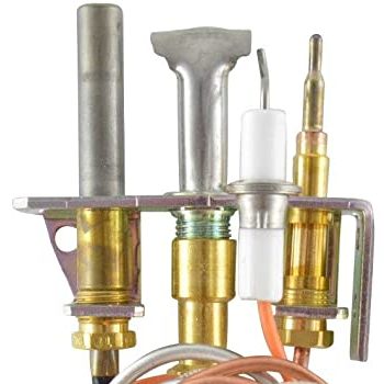
The end of the thermopile wire branches off into two leads usually in red white colors. It is typically used in conjunction with the Q313 Thermopile Generator in a variety of Pilot. Thermocouple pyrometer grounding thermopile vdo.
The leads of the thermopile will be attached to the main valve. Thermocouple Input Temperature Transmitter Head-mounted - BRIGHTWIN.
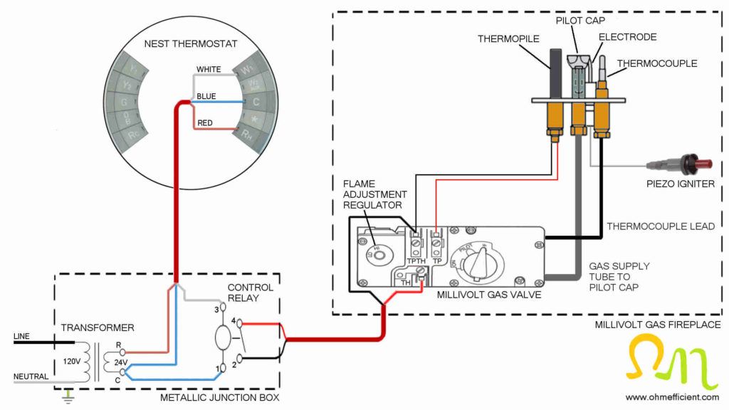
How To Connect A Nest Thermostat To A Gas Fireplace Ohmefficient
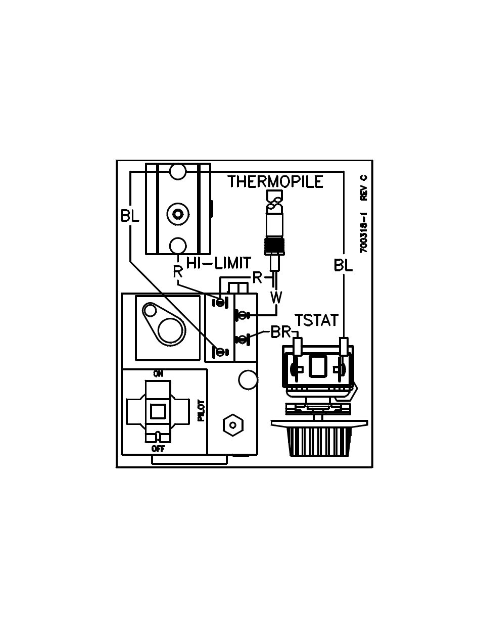
Wire Diagram Pitco Frialator 45c With Millivolt Gas Valve User Manual Page 17 19 Original Mode
Deta 80 Jpg

How To Thermocouple Wiring Connections To Plc Diagrams

Thermost Wiring Ac Service Tech

Thermopile What Are They And How Do They Work Electrical4u

Amazon Com Durablow Sh3001 Rh Gas Fireplace Wifi Smart Home Remote Control For Millivolt Valve Ipi Module Works With Amazon Alexa Google Home Samsung Smartthings Ifttt Siri Home Kitchen

Gas Fireplace Remote Control Buying Guide Fireplaces Direct Blog

How To Thermocouple Wiring Connections To Plc Diagrams
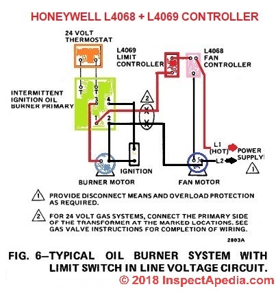
How To Install Wire The Fan Limit Controls On Furnaces Honeywell L4064b All White Rodgers Fan Limit Controllers
How To Test Your Thermopile Www Mygasfireplacerepair Com

How To Thermocouple Wiring Connections To Plc Diagrams
How To Test Your Thermopile Www Mygasfireplacerepair Com

Do Not Use This How To Wire Pid Controller Pls Check Out The Updated Version In The Description Youtube

Rotax Ducati Ignition Wiring Diagram Rotax Aircraft Engine Ducati Ignition Wiring Diagram
How To Test Your Thermopile Www Mygasfireplacerepair Com
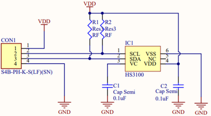
Hs3003 Mc1 Relative Humidity And Temperature Sensor Module 2 5 Rh Accuracy Renesas